 HWR Workholding USA is renowned of their INOLine® workholding of lathes and their OLIDLine® product group of 52/96 workholding products for 5 axis CNC milling. Hemlock MI – Great Lakes Tooling Solutions is thrilled to announce its recent appointment as the exclusive Manufacturers Agent for HWR Workholding USA in the state of Michigan. This strategic partnership brings together the innovative workholding solutions from HWR and the regional expertise of Great Lakes Tooling Solutions, providing Michigan manufacturers with access to cutting-edge technology designed to reduce set up and changeover time and increase productivity. HWR Workholding USA is renowned for its INOLine® product range, featuring advanced solutions like INOFlex®, INOZet®, and INOTop®. These versatile workholding products empower manufacturers to achieve precision clamping within CNC lathes across a diverse range of workpieces, reflecting HWR's commitment to delivering adaptable and efficient machining solutions. The SOLIDLine® product group stands out as a cornerstone of HWR's offerings, specifically tailored for 5-axis workholding systems. Comprising SOLIDClick, SOLIDGrip, SOLIDPoint, SOLIDBolt, and SOLIDChuck, each component within this product group is meticulously designed to provide exceptional precision, versatility, and efficiency in 5-axis machining operations.
This exclusive collaboration positions Great Lakes Tooling Solutions as the go-to resource for manufacturers in Michigan seeking access to HWR's cutting-edge workholding technology. With a commitment to delivering exceptional products and services, Great Lakes Tooling Solutions is poised to drive the adoption of HWR Workholding solutions across the region. For more information on HWR Workholding USA's product offerings and the collaboration with Great Lakes Tooling Solutions, please visit HWR Workholding USA landing page on our website. About HWR Workholding USAHWR Workholding USA are specialists in clamping deformation-sensitive workpieces and in compensating, concentric clamping of components of any shape. Your application in focus: With more than 30 years of experience, we know your applications exactly – and always focus on your requirements in our develoments. At HWR the power of innovation meets absolute precision in execution. The result: application-optimized clamping devices that reliably meet the increasing demands in turning operations. Rely on effective and low-cost solutions for optimal production results. About Great Lakes Tooling SolutionsGreat Lakes Tooling Solutions is a prominent manufacturers agent specializing in providing cutting-edge solutions to the machining industry. With a focus on delivering top-tier products and unparalleled service, Great Lakes Tooling Solutions serves as a key conduit between manufacturers and innovative technologies that they introduce to machine shops.
0 Comments
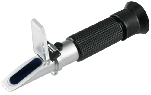
Compiled & Edited by Bernard Martin In the metalcutting world where tool life and surface finish can define profitability, refractometers play a crucial role, providing a reliable means to gauge the concentration of water based coolants. Advanced Chemical Solutions (ACS), based in Orrville, Ohio, offers a range of refractometers designed for various applications. This article will walk you through the steps of calibrating, using, and reading ACS refractometers to ensure accurate and consistent results in your chemical analyses. 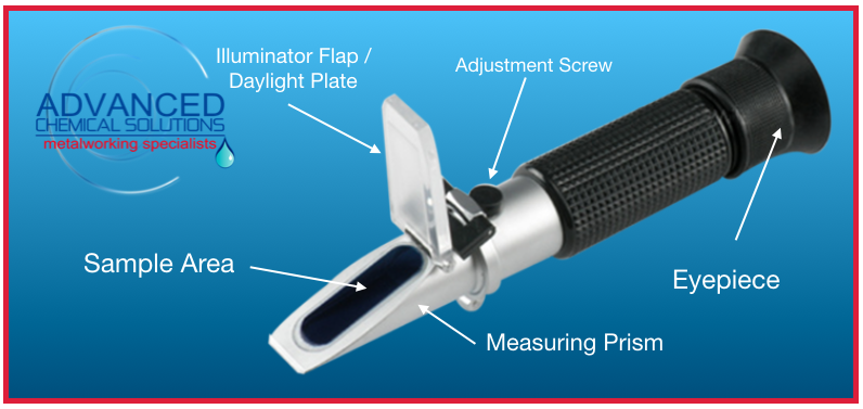 CalibrationBefore diving into measurements, it's essential to calibrate your refractometer to guarantee accurate readings. ACS refractometers typically come with clear calibration guidelines. Begin by cleaning the refractometer prism with a gentle cleanser, ensuring there are no residues that could impact readings. Next, use distilled water to set the refractometer to zero by adjusting the calibration screw. ACS refractometers may also include calibration solutions specific to certain industries; be sure to follow the recommended calibration procedures outlined in the user manual. Using the RefractometerTo prepare your coolant sample for refractometer measurement, it is crucial to ensure that the sample temperature matches that of the refractometer, guaranteeing accuracy in readings. Apply a small quantity of the coolant solution onto the refractometer prism, forming a thin film for analysis. Once the sample is applied, gently close the cover plate to evenly spread the water-based coolant across the prism. Next, Position the refractometer towards a light source, and peer through the eyepiece to observe the sample. Adjust the focus until the interface between light and dark areas is sharp and well-defined, optimizing the conditions for precise and reliable measurements. Reading the Refractometer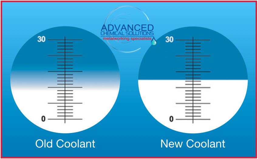 When reading the refractometer, begin by locating the interface—the boundary line between the light and dark areas on the refractometer scale. Next, read the concentration value at the point where the interface intersects the refractometer scale. ACS refractometers commonly present values in units such as Brix, refractive index, or other industry-specific metrics. To account for temperature variations, especially if your refractometer lacks temperature compensation, it is advisable to apply a correction factor based on the sample's temperature. This step ensures the accuracy of your readings and aligns the measurements with the desired standards for precise analysis. Advanced Chemical Solutions' refractometers provide a precise and efficient means for measuring concentrations in various solutions. By following the calibration, usage, and reading guidelines outlined in this comprehensive guide, you can ensure reliable and consistent results in your chemical analyses. For specific details regarding the operation of your ACS refractometer model, always refer to the user manual provided by ACS. ACS RefractometersAdvanced Chemical Solutions' Refractometers are precision optical instruments used for measuring concentrations of substances in aqueous solutions not just coolant. They work by using the principle of light refraction through liquids. Refractometers measure concentration and oil emulsion. Concentration will appear as the horizonal line on the brix scale. Click on the image to learn more. Manual Refractometer
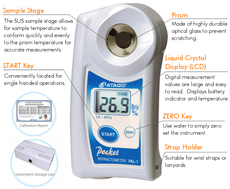
Digital Refractometer
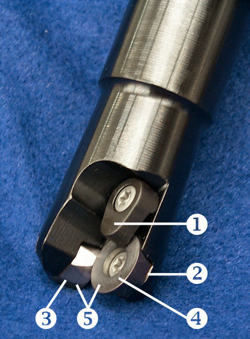
The round-insert "button cutter" can bring a high metal removal rate to a low horsepower machining center. By Michael Bitner, Dapra Corporation. This article originally appeared in Modern Machine Shop. This article originally appeared in Modern Machine Shop. 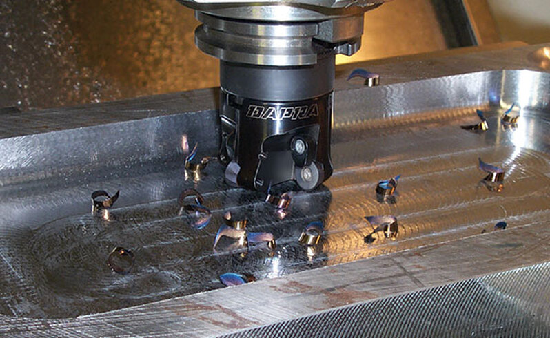 A 6" by 12" pocket, 1.25" deep, was cut on a 15 hp, 40 taper machining center using the copy milling cutter shown. Parameters were 2,200 rpm, 250 ipm and 0.035" depth. Cycle time was 8 minutes, 18 seconds The work of indexable milling tools is often accompanied by vibration that is a familiar sound – and a familiar feel – in many shops. When these tools are run at heavy depths of cut to achieve high metal removal rates, the productivity may come at the expense of the corner of the cutting tool and the life span of the machine. One alternative that can provide a smoother cut, in addition to many expanded capabilities, is the copy mill. "Button cutter" is another name for this type of tool. The copy mill is a simple variation on the traditional end mill, in that the copy mill uses circular insert geometry as opposed to traditional parallelogram or square inserts. This difference delivers a variety of benefits, most of which complement today's trend toward lighter depths of cut and faster feed rates, or high speed machining. This article discusses each of these benefits individually. PlungingSome copy mills possess the ability to plunge directly into the material, similar to a drill. This is particularly true of the end mill version of the copy mill, but only where the manufacturer has built in sufficient clearance on the bottom of the tool to permit cutting in this direction. Direct plunging is also possible with a shell mill version of the tool, but most shops would find this to be such a large horsepower drain that they would be better off ramping. A copy mill can't take the place of a drill; the surface area engaged is too large to continue this way much beyond the desired depth of cut for milling. However, the ability to plunge during milling removes a common machining headache: the need to drill a start hole prior to roughing. A conventional indexable end mill requires this drilled start hole because the tool is not able to execute a straight Z-axis move into the material. The only other way to enter the material with this type of cutter is a ramp-in entry, which typically calls for CAM software. However, with a copy mill, this step can be avoided. Plunging can be programmed into the control's canned pocketing cycle without concern for the tool's entry. This freedom to plunge is particularly helpful in more complex cavity roughing or surface roughing routines, where a CAM package may interject numerous plunge points in order to complete the roughing tool path. With copy mill cutting tools, these plunge points are no longer a concern. Helical Interpolation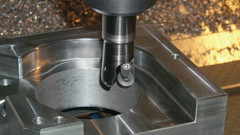 The 4" dia. hole shown here was machined in 4140 steel using a 1" diameter copy mill at 4,000 rpm, 200 ipm and 0.035" depth of cut. Larger diameter hole making can be quick and easy when a copy mill is used in combination with helical interpolation. This technique resembles thread milling in that all three axes (X, Y and Z) are in motion simultaneously. It differs from thread milling in that the tool is introduced into the material without a start hole of any kind. The tool simply is positioned at the inside diameter of the hole to begin its helix from there, achieving complete material removal from the hole by ramping down to the final depth. This smooth operation tends to avoid the high horsepower consumption characteristic of large diameter hole making. And with the high clearance angles of copy mill cutting tools, ramp angles during helical interpolation can be aggressive, without concern for rubbing the bottom of the cutting edge. The quick and easy process offers the added advantage of allowing many different hole sizes to be generated with the same diameter tool. Hole size variation is all in the programming. Edge StrengthWith no corners to break, a round insert provides the strongest cutting edge available in an indexable carbide insert. The strength comes in handy when operating in a heavy cut, or when attempting roughing cuts under unstable conditions. When cutting with a long-reach tool, the round inserts are more forgiving of tool deflection and chatter, allowing speed and feed rate to be increased with less danger of insert chipping. Cutting forces are also distributed more effectively. With a typical 90-degree cutting tool, the majority of the tool pressure is radial, resulting in high deflection and increased potential for chatter or breakage. The round cutting edge spreads the force more evenly, directing a larger percentage of the tool pressure into the axial direction. This too is desirable when cutting with longer-length tools, because the reduced radial pressure reduces deflection. But beware of this condition when using a horizontal machining center. The increased axial pressure may cause flexing in the workholding, which typically is mounted on a tombstone or angle plate that isn't as well supported as the solid base of a vertical machining center. On an HMC, this flexing can result in micro chipping of the insert from the subtle vibrations that occur with the flex. Tool life will be shortened, and cutter breakage is more likely. To reduce or eliminate this problem, try positive axial rake cutters, which minimize the downward push into the workpiece. Number Of EdgesRound inserts provide the additional benefit of offering a larger number of usable edges than typical carbide inserts. Depending on the size of the insert and the depth of cut, a round insert can provide from four to eight effective indexes, yielding at least twice the total material removal and minutes in the cut of a typical parallelogram or square. This advantage translates to fewer trips to the tool crib for new inserts (keeping the operator at the machine and the tool in the cut), fewer inserts to stock in inventory (lowering on-hand inventory costs) and a lower cost per cutting edge. For example, the typical parallelogram insert costs about $8. With two usable edges, the cost per edge is $4. A square insert (which usually does not perform as well as a parallelogram because of the lack of a positive topography and axial relief) may cost $10. This comes to $2.50 per edge. Compare these costs to that of a typical round insert. This insert may cost as much as $11 (many are less). At this cost, the worst-case scenario – heavy cutting permitting only 4 indexes — yields a cost per edge of $2.75. The more typical scenario, 8 indexes, yields a cost per edge of $1.38. These costs, particularly in applications where the round insert delivers more metal removal per minute than other inserts, make the economics of the tool attractive. 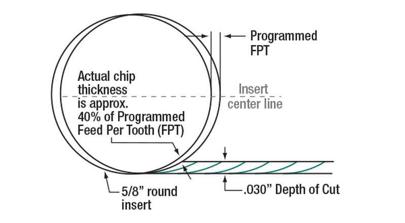 Fig. 1 – Round inserts cut more efficiently at light depths. A light depth of cut decreases the chip thickness and therefore decreases the horsepower demand. Metal Removal With Low HorsepowerApplied correctly, round inserts can yield impressive material removal rates without a demand for impressive horsepower. The strength of a round insert permits feed rates that would not be possible with 90-degree cutting tools, allowing even lighter-duty machines to perform aggressive roughing. The key point to understand with a round insert used in this way is that heavier depths of cut lead to higher chip thickness, which increases horsepower consumption. (See Figure 1.) By taking light cuts – 0.025 to 0.050 inch depth of cut – the typical round-insert cutting tool can feed at rates in steel around 0.040 inch per tooth, and in certain cases as high as 0.060 inch per tooth. By comparison, most parallelogram or square inserts reach their limit at 0.010 to 0.012 ipt. It is important to note that some users of button cutters have experienced problems with insert movement in the pocket of the cutting tool during cutting, or when the insert is worn. In either of these cases, tool pressure increases and the effectiveness of the insert clamping can be compromised. The cutter should include design characteristics that strengthen tool integrity for these applications. Some cutters, for example, use screw-through inserts accompanied by extra top clamps. These cutters provide the security of double clamping for each insert. Another important feature is positive locking in the insert seat. Many button cutters use inexpensive molded inserts that have round sides, providing no radial locking for the insert. Tangential cutting forces on an insert such as this may cause the insert screw to lose torque. More rigid copy mills address this problem with locking surfaces on the sides of the inserts — locating flats that mate with matching flats on the cutter body, leaving little chance for movement. 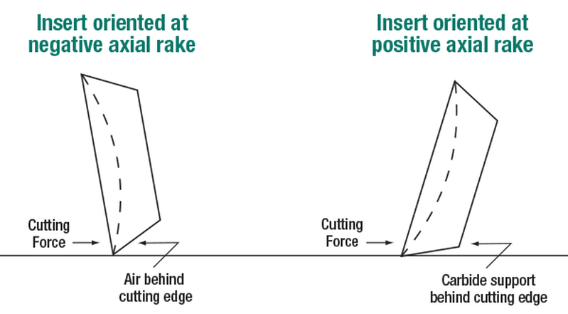 Fig. 2 – Copy mill cutters using positive axial rake provide a smoother cut and better cutting edge support. Finally, look for tools providing maximum support for the cutting edge, particularly if high feed rate is the goal. Copy mill cutters using negative axial rake (tipping the insert down toward the workpiece) can cut well using conservative parameters but fall short during more aggressive metal removal. Inherent in the design is a lack of support for the primary area of force, which is right at the cutting edge. (See Figure 2.) Copy mill cutters using positive axial rake provide much better cutting edge support because the carbide behind the cutting edge is closer to being parallel with the cut. Positioning the carbide in this way lets the end user take advantage of the carbide's ability to absorb high compressive forces. But in this scenario, toolholding rigidity is important. Stub-length end mill holders or shell mill holders are highly recommended. With the right tooling, even machine tools with only 10 or 15 hp are capable of competitive metal removal, resulting in fewer setups and greater flexibility in shopfloor scheduling. Roughing Closer To Finish FormThe use of a round insert for roughing applications opens up new possibilities in the preparation for semifinish or finish cuts. When roughing with 90-degree cutters, each step down (or each pass during Z-level roughing) leaves a "stair step" behind.
Automating challenging parts for full-weekend automation requires substantial process refinements that can significantly boost throughput thanks to Agile Robotic EVAN DORAN, Associate Editor, Modern Machine Shop 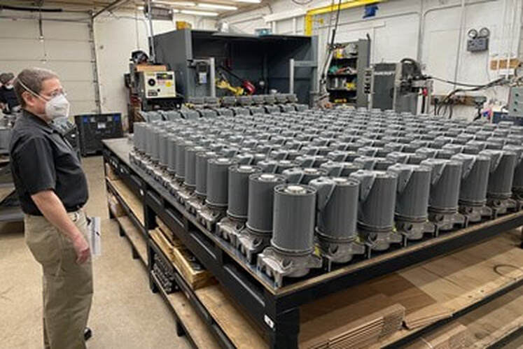 MTH Pumps’ assembly area currently doubles as a storage area for completed Freon pumps. The company’s robotic welding cells (visible in the back) not only automate the assembly process, they also conduct operations that would be impossible by hand. MTH Pumps is filled to capacity. The Plano, Illinois, pump OEM has outfitted its shop floor and adjacent building with machine tools, storage racks, quality control devices, welding robots and more. Spatially limited in its ability to expand its fleet of machines to meet skyrocketing customer demand, the company is turning to a series of creative solutions — including but not limited to automation — to increase productivity and throughput. Adding machine-tending robots to its Mazak Integrex multitasking machines was the first step along the company’s automation journey, but meeting increased customer demands has also required a series of process refinements and strategies around redundant machines and tooling, process repeatability and bespoke part-staging setups. These strategies have not only allowed MTH Pumps to ramp up production and achieve lights-out automation, they have done so without reliance on heavy expenditures toward capital equipment. Boilers, Chillers and FreonMTH Pumps first opened its doors in 1965. Second-generation owner Tim Tremain cut his teeth with the company in the 1980’s, and has been on the forefront of the company’s automation efforts since programming a two-pallet horizontal machining center at the start of his career. The company uses castings to create more than 3,000 part numbers, though the bulk of its work involves variations of three parts for the company’s line of regenerative turbine pumps. These pumps are comprised of casings (consisting of cover and motor bracket components) and impellers, with rings for multi-stage pumps. The casings are typically bronze, stainless steel or cast iron, while the impellers are commonly made of bronze or a high-nickel ASTM A494 alloy. While demand for these pumps has been steady across the longstanding boiler feed and chiller markets, MTH has seen a massive uptick in demand for sealless versions of its pumps for computer data centers and other customers using Freon cooling systems. Even on parts without the zero-seal requirement, many of MTH’s machined parts need to hold extreme tolerances, such as its impellers that require 0.0005” tolerances for perpendicularity, parallelism and flatness at thicknesses of 0.082”. In 2006, the company’s drive toward improved quality led it to purchase its first turn-mill, a used Mazak Integrex 200-IIIST, to counteract the holdups and inaccuracies resulting from transfering parts between machines. While moving parts between spindles in the Integrex still requires multiple chuckings, Tremain says the automated nature of the second chucking makes the multitasking machine “an order of magnitude” better for quality than the hand-loaded positioning and hand-tightened clamping devices of the HMCs and lathes previously used by the company. 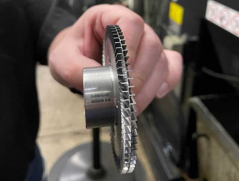 “The impeller is the heart of the pump,” Tremain says. But the impeller’s ubiquity doesn’t make its 0.0005” perpendicularity and parallelism tolerances any simpler to machine, especially at a thickness of 0.082”. The Integrex machines must mill vanes on each side separately without disrupting the perpendicularity-parallelism tolerance relationship. MTH’s first Integrex machine made such a difference to the company’s processes that the OEM gradually replaced the bulk of its single-operation machines with 12 Integrex multi-tasking machines of various sizes and eras. Each of these machines includes built-in automation features such as deburring brushes and three-axis gantry robots. The company has also paired one of its machines with a six-axis machine-tending robot from Agile Robotic Systems, combining the gantry robot and the machine-tending robot into a single cell that facilitates overnight and full-weekend stretches of lights-out automation. To put the productivity of the multitasking machines into perspective, the company produced 62,000 parts in 2009 (one year after the MTH team had gained enough experience with the Integrex to begin using it for full production). In 2016 — with the same number of machinists but with most of the older mills and lathes replaced by turn-mills — the company produced 145,000 parts, more than doubling its production during this period. Even this increased productivity is not enough to handle the demand for Freon pumps, however. Not only have new customers been coming to MTH for these pumps, but the company’s largest Freon pump customer also plans to quadruple its monthly orders. Using its previous production methodologies, this increase would have required MTH Pumps to double the number of its machine tools. But when MTH began to assess current machine utilization rates, it became clear that increasing machine utilization was the company’s best option. A 2021 machine utilization study using Vimana’s machine monitoring software found MTH’s machines were achieving a 25% utilization rate over a 24/7 period. For years, this level of utilization hadn’t been a problem because the manufacturer still maintained an impressive 95% on-time delivery rate — an achievement largely due to MTH’s ownership of a small foundry that enables the company to bypass the delays facing other manufacturers making parts from castings. But with a significant increase in customer orders, 25% machine utilization would be untenable. The realization of just how much machine capacity was going unused spurred MTH toward process optimization. Its first move was to begin monitoring shopfloor production metrics and setting benchmarks through the Vimana platform, troubleshooting whenever cycle times for a part lengthen over historical standards. Next came the task of determining how to keep MTH’s machines running longer, with an ultimate goal of full-weekend unattended machining. Approaching this goal required multiple changes that bolster lights-out repeatability, from setting up machine and tool redundancies to experimenting with workholding strategies. 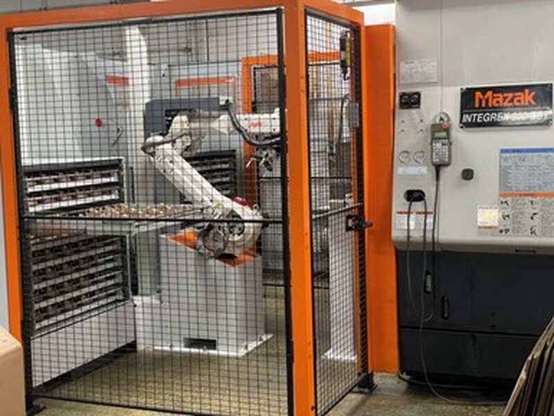 MTH Pumps achieves lights-out automation overnight through pairing its 12 Mazak Integrexes with auto-loading gantries. One Integrex is also paired with a machine-tending robot from Agile Robotic Systems, and the combination of machine-tending robot and gantry loader extends this machine’s unattended operations over the weekend. Irreplaceable RedundanciesBefore the refinement push, MTH Pumps ran a two-shift shop five days a week, with a third shift of lights-out automation. Extending this automation over the weekend required two core changes. First, the company needed to program its machines’ RenishawRMP600 probes to automatically determine when to perform redundant tool changes. The probes do this by measuring parts and triggering cutter compensation and tool length adjustments to account for tool wear, remachining part features immediately if they are out of tolerance. When the tool reaches a certain overall limit of tool size adjustment, the machine performs a redundant tool change and resets the adjustment limit to zero. The second change built on the first: MTH needed to stock enough redundant tooling in each machine to ensure it can operate as long as possible — whether that is overnight or from the close of business on Friday to the beginning of Monday’s first shift. A freelance consultant helped MTH accomplish the first task simply enough. On the surface, MTH Pumps’ Integrex machines seemed like they would make the second task — providing redundant tooling for long stretches of lights-out machining — equally straightforward. Depending on the model, Integrex machines contain 110- or 120-tool magazines, and the cost of supplying redundant tooling wasn’t much of a concern given the increased production these tools would enable. Challenges arose from the hard metals the company machines. While automating bronze parts over the weekend doesn’t require many tool changes, stainless steel parts (such as the Freon pump parts) and cast-iron parts chew through tools at a much higher rate. Another difficulty? While the Integrexes have large tool magazines, increasing productivity requires all parts to be compatible with two or three machines so that production can flex for large orders or compensate for maintenance downtime. As part of ensuring compatibility, each machine that might be assigned to a specific part must be stocked with the tooling and programs for that part. To this end, the company has standardized its tooling mixes across machines, with tool locations identical between machines whenever possible. Tremain says the machines working on stainless steel parts have not yet completed a full, unattended weekend of production, but their success in doubling runtime through the night and tripling runtime through the weekend has been a significant boost to MTH’s utilization and productivity. 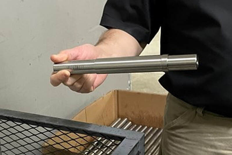 While MTH’s multi-tasking machines can perform the deep drilling vital to producing Freon pump shafts, Tremain describes using the 12”-chuck Integrex to machine a 1”-diameter shaft as “overkill.” As such, the OEM is on the lookout for Swiss-type machines with deep drilling capabilities to produce the part. Consolidation and Cycle TimesHeading up this standardization and optimization effort is Charlie Ruetsche, a freelancer running the consulting business Refined Manufacturing. Ruetsche is a former Mazak applications engineer, which makes him well-suited for improving the program repeatability and cycle times on MTH’s Integrexes. Ruetsche’s first refinements for the Freon pump began with MTH’s tool consolidation efforts, during which he programmed the probing operations and experimented with different inserts and geometries to find the best combination of performance and durability for each operation. He also refined the company’s programs using advanced features of its ESPRIT CAM software such as Profit Milling, which creates roughing programs with light radial engagement and full depth of cut to reduce cycle times and improve tool life. These tooling and programming refinements have added up to massive improvements in cycle time. Reaching a target of 75 Freon pumps per day used to be impossible — even with overnight automation — as machining operations for the casing alone clocked in at 62 minutes per part. Ruetsche’s alterations cut the cycle times for this part nearly in half, making the OEM’s goal achievable with two machines simultaneously working on the part. According to MTH’s March 2022 data, the company’s automation refinements have resulted in a 60% increase in motor brackets, covers and impellers per labor hour, with more to come.Stacking a Complete SetMost of MTH’s gantry loaders utilize either a stacker-style or pallet-style table system. The stacker-style gantry table systems can hold stackable raw material such as impeller blanks, of which it fits up to 320 at a time. The pallet-style gantry table systems with nesting boards hold non-stackable castings such as covers and motor brackets. On most machines, the boards for the pallet-style system can only hold up to 36 parts at once. The machine with the six-axis robot expands the pallet-style system to a drawer-style tray system that feeds non-stackable parts to the gantry robot, which then loads the machine. MTH currently uses this drawer-style system to facilitate production of up to 320 covers or motor brackets at a time for its smallest model of regenerative turbine pump. While the drawer-style system enables the OEM to produce covers or motor brackets lights-out over the weekend in a one-to-one ratio with impellers, it must still machine the corresponding casing component during the week due to differences in workholding between the cover and the motor bracket. This requires MTH Pumps to keep the two batches of 320 components in inventory until the remaining component batch is complete. Tremain says the next step of optimizing his company’s workholding setup is ensuring that its covers and motor brackets are made in a fully one-to-one ratio. To do so, the company plans to put more than one component type on each nesting gantry board. While standard gantry boards are not designed for use with multiple parts, MTH is already accustomed to using custom gantry boards with slots to fit part feet. When I visited MTH in March 2022, its in-house engineering staff had developed a prototype pattern for the multi-component gantry board and was making test gantry boards with a small milling center in its toolroom. Ultimately, MTH hopes both to stage the two halves of a pump casing on the same gantry board and to alternate between them. As long as the workholding and the gantry loader’s grippers are the same between parts — and as long as the machining center holds the proper programming and mix of tooling — this could become a reality. If the OEM can go a step further and add impellers, it would then be able to include a full unit on its gantry boards. This would spark a massive change for MTH Pumps’ inventory, as the company would no longer need to keep a stock of extra parts waiting for the rest of the components. 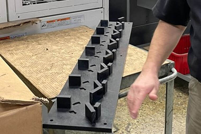 MTH Pumps engineers and machines some of its custom gantry boards in-house. The P-Factor is the X-FactorIn the period between MTH Pumps’ initial utilization audit and my visit, the OEM had already increased its machine utilization rates from 25% to 30%. A 5% increase may not sound like much, but in conjunction with a 50% cycle time reduction across multiple major components, this has resulted in a major productivity boost.
This stark difference between utilization and cycle time improvements is actually quite normal, says Robert McCrory, MTH’s director of operations. He explains that until demand increases, cycle time reductions can make utilization look unfavorable by reducing the amount of time the machine will need to run for the same output. Neither utilization nor cycle time by itself is a perfect metric for measuring MTH Pumps’ improvement, then. As a result, McCrory has started to prefer a metric measuring the parts produced per labor hour, which he calls the “P-factor.” According to MTH’s March 2022 data, the company’s automation refinements have resulted in a 60% increase in the P-factor for motor brackets, covers and impellers, with more to come. “We’ve probably got fewer machinists right now than we did in the ’80’s,” Tremain says, referring to the earliest days of MTH Pumps’ automation efforts. “But we’re easily making 15 times as many parts today.” FOR IMMEDIATE RELEASE  Great Lakes Tooling Solutions, a trusted manufacturer's representative agency serving industrial distribution in Michigan, is pleased to announce its exciting new partnership with Agile Robotic Systems, a leading supplier of innovative machine loading systems for manufacturers worldwide. This strategic collaboration opens up a world of possibilities for businesses seeking cutting-edge CNC Machine Tool Loading Systems, Robotic Automation Systems, and CNC Workholding solutions.
Great Lakes Tooling Solutions has earned a reputation as a premier representative agency in Michigan, providing exceptional service and top-quality industrial products to its clients. By teaming up with Agile Robotic Systems, they are further expanding their offerings to address the evolving needs of the manufacturing industry. Agile Robotic Systems is renowned for its state-of-the-art solutions designed to boost manufacturing efficiency and productivity. Their portfolio includes CNC Machine Tool Loading Systems, which enhance automation and reduce downtime, Robotic Automation Systems that streamline production processes, and CNC Workholding solutions that improve workpiece stability and precision. This partnership between Great Lakes Tooling Solutions and Agile Robotic Systems reflects a shared commitment to delivering the latest advancements in industrial technology to their valued customers. Manufacturers across Michigan can now benefit from cutting-edge solutions that help optimize their operations and stay competitive in today's fast-paced market. "We are thrilled to join forces with Agile Robotic Systems, a company at the forefront of innovation in the manufacturing sector," said Justin Verburg, one of the Partners at Great Lakes Tooling Solutions. "Our combined expertise will empower Michigan businesses to harness the power of automation of their CNC Machines and robotics, driving greater efficiency and profitability." The collaboration promises to provide Michigan machine shops and manufacturers with access to a comprehensive range of CNC machining automation solutions that cater to various process improvement needs. Great Lakes Tooling Solutions and Agile Robotic Systems are committed to delivering outstanding customer support and tailored solutions to help businesses thrive in an ever-evolving manufacturing landscape. For inquiries, please contact us Great Lakes Tooling Solutions Appointed Manufacturers Agent for ACS - Advanced Chemical Solutions9/6/2023 FOR IMMEDIATE RELEASE  Hemlock, MI — Great Lakes Tooling Solutions proudly announces its recent appointment as the exclusive manufacturer's agent for the state of Michigan by ACS - Advanced Chemical Solutions. This strategic partnership enhances Great Lakes Tooling Solutions' commitment to providing cutting-edge solutions for the metalcutting manufacturing industry in Michigan. As a leading provider of innovative tooling solutions, Great Lakes Tooling Solutions will now represent ACS, a renowned player in chemical solutions for the manufacturing sector. ACS is known for its high-quality products and commitment to advancements in chemical technology. Advanced Chemical Solutions understands the importance of providing to our customers "state of the art" fluid technology as well as first class service. They do this by focusing on the product performance, employee/environmental health and wellness and overall operating cost. "We are thrilled to be appointed as the manufacturers' agent for ACS in Michigan. This collaboration enables us to offer our clients access to ACS's state-of-the-art metalworking coolants and lubricants, enhancing our ability to provide better performance and longer tool life in the manufacturing processes," said Brent Slagell at Great Lakes Tooling Solutions. The partnership aims to bring ACS's cutting-edge metalcutting and metalforming fluid solutions to manufacturers in Michigan, fostering efficiency, sustainability, and innovation in their operations. With this collaboration, Great Lakes Tooling Solutions reinforces its dedication to meeting the evolving needs of the manufacturing sector with top-tier products and services. Cools...Cleans...Protects - You made an investment in your equipment, now make sure to maximize it's performance by using our premium industrial fluids. For more information about Great Lakes Tooling Solutions and ACS - Advanced Chemical Solutions, please contact one of our team members. About ACS - Advanced Chemical SolutionsFrom a friendship that started in the first grade and continues to this day, Advanced Chemical Solutions was founded by two industry metalworking lubricant professionals in 2001. Gerry Groudle and David Fidel over sixty years of practical field experience in metalworking fluids.
Gerry and David started with a vision to compete with industry giants by providing better service, cleaner running products, and more employee friendly metalworking fluids. Once they had established a core competency of products, they began assembling a team of high technical people from within the metalworking industry. The objective has been to provide the end-user with resources to manage every aspect of fluid management from large central systems to small shops. Guest Blog by Mark Donze at Fullerton Tool 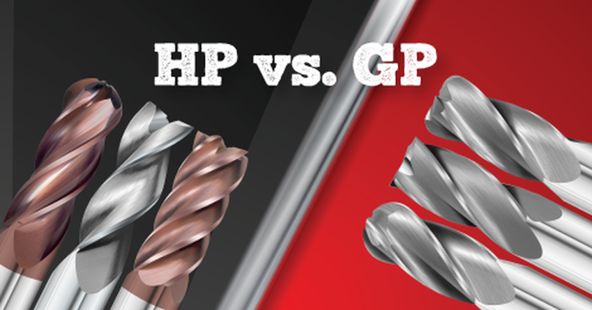 Have you ever wondered if you should purchase high-performance end mills or general-purpose end mills and what the benefit of purchasing one over the other is? If so, we have put together a list of factors to consider to help you make the right decision for next time. General Purpose End MillsFirst, let's discuss general purpose end mills. General Purpose (GP) End Mills are standard single, 2, 3, or 4 flute geometry end mills made for use in a wide variety of materials. Benefits of General Purpose End Mills:
High-Performance End MillsNext, High-Performance (HP) End Mills contain specialized geometries for a specific material being cut.
Benefits of High-Performance End Mills:
With this information in mind, if you are a company that does small runs in a wide variety of materials you may prefer GP end mills. Whereas, if you are making high-volume parts where cycle-time and up-time are king, you may prefer an HP end mill for your use. Remember, there are no hard lines drawn. Each application is different and preference is ultimately up to you, the end-user. If you aren't sure, you can contact your Fullerton authorized distributor to help make this decision. We will work with you to get the end results you desire with a wide variety of both GP and HP end mills available. We even have some tooling where we apply HP coatings to GP tools to help you get the most out of your cutting tool investments. We have a huge selection of inventory items and of course, if you need a special tailored tool to your specific needs, we have engineering and application knowledge to get the most out of your cutting tool budget. We also have resources on our website to help you navigate which tool is the best for your needs. Discover what end mills are recommended for your material and application by using the Fullerton Tool End Mill Selection Guide You can also explore and search for tooling by material, application, or tool specs as well as recommended speeds and feeds by series which you can access at the search button below. compiled and edited by Bernard Martin 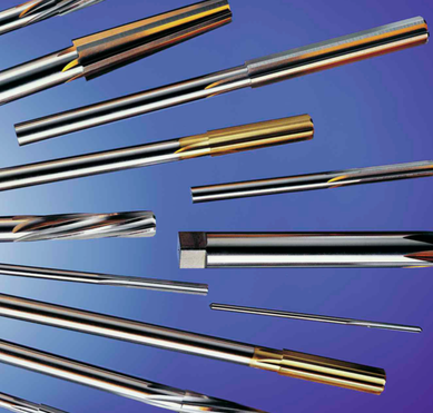 Tri-Angle Precision Reamers has a large inventory of standard diameter reamers, in both High Speed and M-42 Cobalt, Reamer Sets and Dowel Pin Reamers as well as custom manufactured specials. Tri-Angle Precision Reamers has a large inventory of standard diameter reamers, in both High Speed and M-42 Cobalt, Reamer Sets and Dowel Pin Reamers as well as custom manufactured specials. In the realm of precision machining, where accuracy and quality are paramount, the proper utilization of cutting tools is a skill that stands as a cornerstone. Among these tools, the reamer plays a crucial role, allowing machinists to achieve tight tolerances and impeccable surface finishes. This article delves into the fundamentals of using a reamer in a CNC machine, shedding light on the various types of reamers and the ideal flute configurations for different material groups. If you need more information, give us a call and we can talk about some solutions for your reaming needs from Tri-Angle Precision Reamers. Understanding the ReamerA reamer is a cutting tool primarily designed to improve the accuracy and finish of drilled holes. It operates by enlarging and shaping a previously drilled hole to meet specific tolerances. Unlike a drill bit that solely removes material, a reamer enhances the hole's precision, roundness, and surface finish. Reamers are commonly used in industries such as aerospace, automotive, medical, and manufacturing, where intricate designs and tight tolerances are vital. Types of Reamers
Preferred Substrate for ReamersThe choice of substrate material for reamers is crucial in determining their durability and performance. Here are some preferred substrate materials for specific material applications:
Flute Configurations for Specific Material GroupsChoosing the right flute configuration is paramount when using reamers in CNC machining, as it affects chip evacuation, heat dissipation, and tool life. Here are some recommendations based on material groups:
Reamer Usage Tips
Reamers stand as indispensable tools in the arsenal of precision machining. By understanding the different types of reamers and selecting the appropriate flute configurations for specific materials, CNC machinists can achieve impeccable results, ensuring tight tolerances and exceptional surface finishes. With proper preparation, lubrication, and adherence to recommended speeds and feeds, mastering the art of reaming can elevate the quality of manufactured components to new heights of precision. Below, take a look at the video about reamers from 1942. The fundamentals still apply to this day! 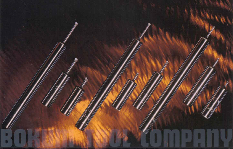 Bokum Carbide Neck Boring Tools AdvantagesBokum Tool's boring tools have 180" of effective regrinding life. For every 1⁄4" of grinding area there are approx. 15 regrinds (assuming average regrind of .015"). This translates into longer tool life at a greater savings than today's inserts. Tools can be reground using Bokum's BSC3-16 resharpening fixtures with the use of a surface grinder, or tools can be resharpened at the plant for a nominal cost.
Loaded with engineered features
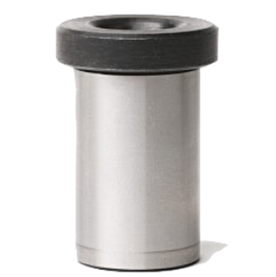
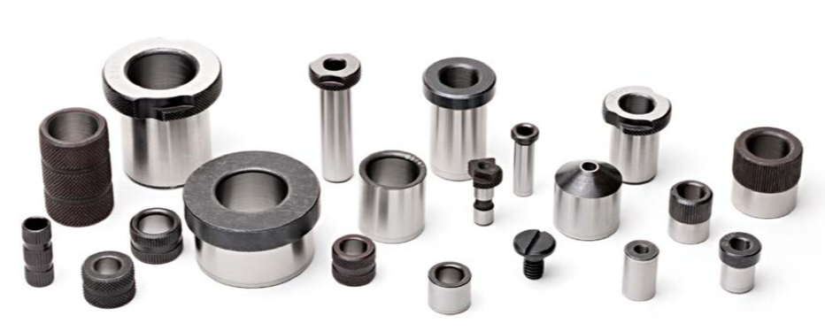 Renewable Drill Bushings are ideal for high production environments or where rapid change over of hole size is required. The bushing can replaced at ‘end of life’ easily by unlocking the bushing and slipping it out the liner.
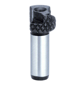
Slip-Fixed Renewable Drill Bushings – SFSlip-Fixed Renewable Drill Bushings incorporate two features on one bush. Used in conjunction with liner bushes, and can be held in place by a lock screw, tenon or stop pin. The are available in both imperial and metric.
Slip-Fixed Renewable Thin Wall Bushings – SF-TWSlip-Fixed Renewable Thin Wall Drill Bushings incorporate two features on one bushing. The SF-TW thin wall drill bushings allow for greater ID range and space saving on the fixture.
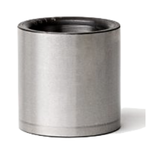
Many drill sizes can be used with one bushing liner. The bushing is rapidly removable after each operation. Both methods are designed to speed up operations and increase productivity. The knurled head allows for easy handling of the bushing to enable it to be rotated out of the removable slip feature Headless Liner Thin Wall Drill BushingsThe Headless Liner Thin Wall Drill Bushings or ‘LTW Type’ have all the features of the ‘L Type’ bushing but with the added feature of a thin wall.
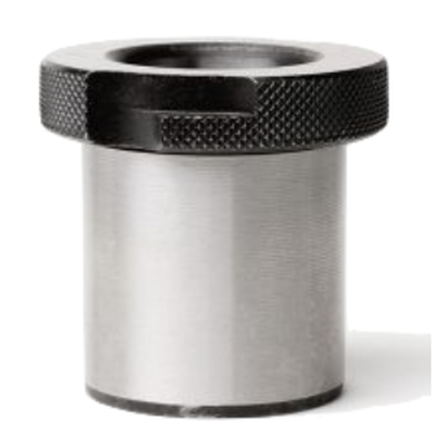
Head Liner Drill Bushing – HLThe shouldered, or head liner drill bushing: can be with countersunk to a flush position or left proud. Head liners are used with fixed & slip renewable drill bushings and are permanently pressed into a drill jig or fixture plate.
|
NEWS UPDATESHere you will find a collection of technical articles and announcements about our principals. Be sure to click on a category below to find all of the articles related to that subject. Archives
December 2023
Categories
All
|

 RSS Feed